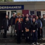
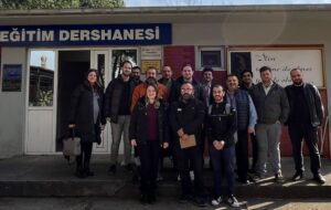
On July 8, 2023, Yıldız Technical University Faculty of Naval Architecture and Maritime Faculty Member Prof. Dr. Ahmet Dursun Alkan visited to see the Tanker Model SERS-T™, which will be the product of SERS™, and the Ship Engine Room SERS™, which is being installed at ITU Faculty of Maritime.
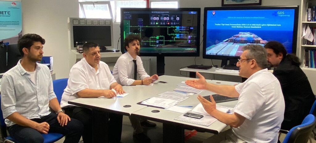
During the meeting at the ITU Maritime Faculty where SERS™, developed by GDS Engineering ARGE, was developed, SERS-T™, which is being developed for the SIRE 2.0 and ISM Code-Based Training of Tanker Type Ship Personnel within the scope of the TÜBİTAK 1501 Project, was introduced. With SERS-T™, a new system will be created to train sailors who will board the Tanker Ship. SERS™, which is actively used during the introduction, was also introduced.
In the developing simulator, Tanker ship machinery systems will be mathematically modeled and Graphical User Interface (GUI) Panels will be designed. The developed simulator will be compatible with SIRE 2.0 and ISM Codes required in Tanker Ships, and seafarers who will work on the Tanker Ship will be able to perform their training with Operation and Management level training scenarios.
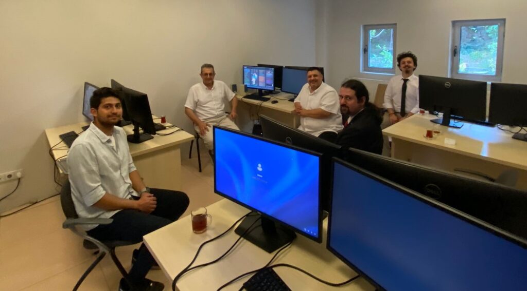
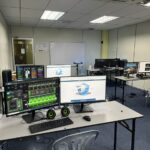
During the visit, the Simulator Center for SERS™, which is being established at ITU Maritime Faculty, was toured.
SERS™ has been pre-installed at ITU Maritime Faculty. SERS™, which was brought to ITU in collaboration with GDS Engineering R&D and SimBT, was highly appreciated by Assoc. Prof. Dr. Ahmet Dursun Alkan. He also shared his own views and recommendations for SERS™ and SERS-T™ with Dr. İsmail Çiçek.
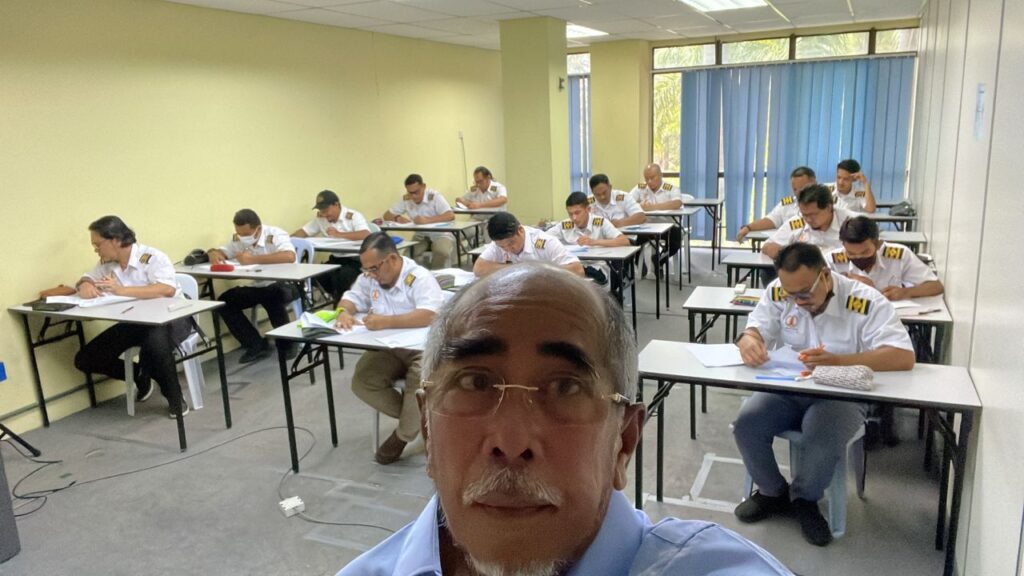
SERS™, which is being installed at ITU Maritime Faculty Simulator Center, will provide training to students from Turkish Maritime schools at ITU Maritime Faculty, thanks to its structure that keeps up with technology for education and its rapid adaptation to today’s ship models, and will ensure that the sector is trained with conscious sailors who are knowledgeable about ship engine rooms.
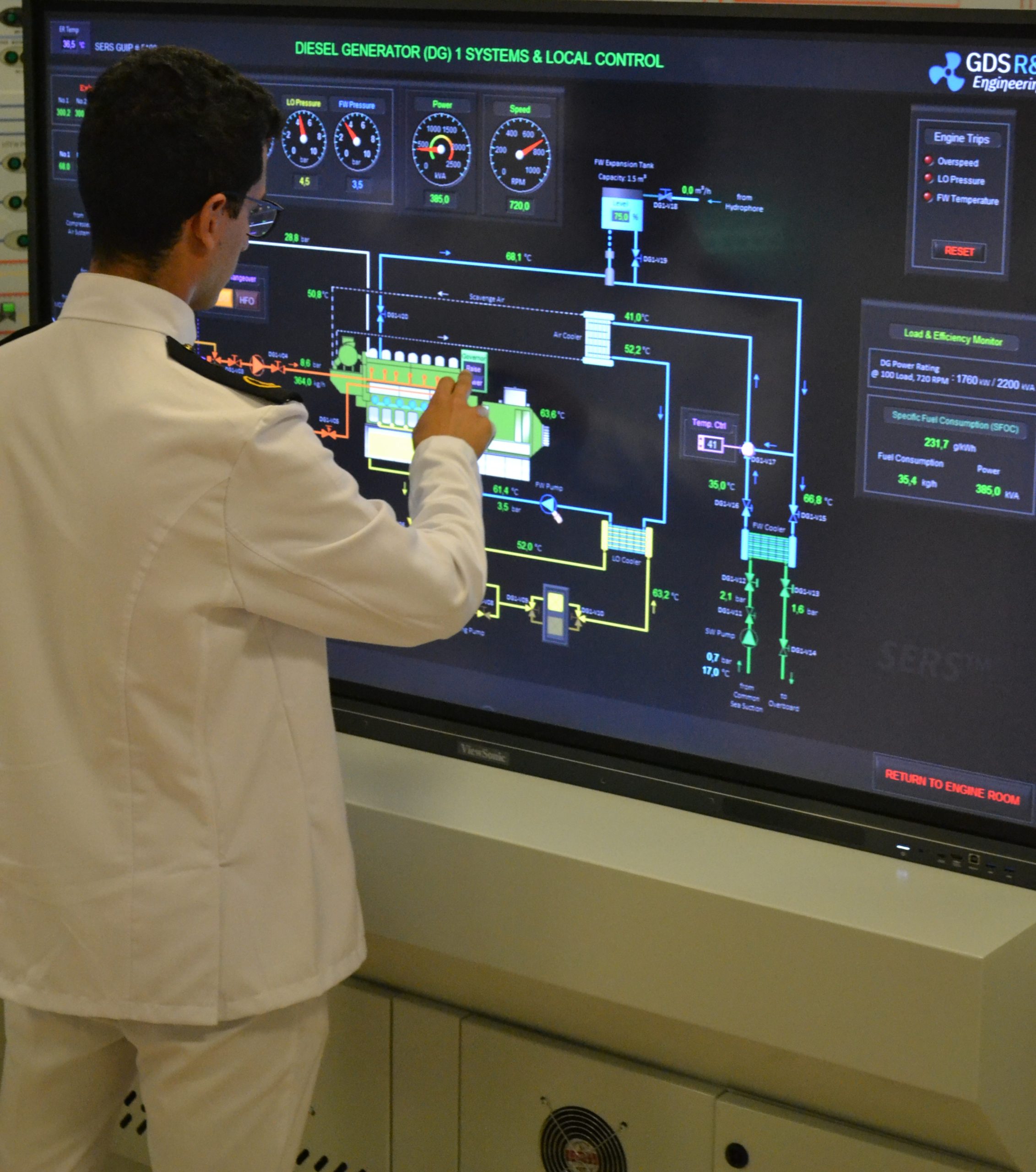
The Role of the GDS Ship Engine Room Simulator in Skill Development
The GDS Ship Engine Room Simulator is an advanced training tool that replicates the engine room environment of modern vessels, providing maritime personnel with hands-on experience in a controlled setting. This simulator covers a wide range of critical systems found in ship engine rooms, including propulsion, auxiliary machinery, electrical systems, and emergency protocols. By using the simulator, crew members can practice their skills, refine their decision-making processes, and gain confidence in handling complex systems without the risks associated with real-world errors.
The simulator allows trainees to engage in realistic scenarios, such as equipment failures, power management issues, and environmental challenges. This training is invaluable in helping them develop deep technical skills needed to respond effectively under pressure. Given the increasing complexity of ship machinery, which often integrates digital and automated controls, such simulator-based training ensures that personnel are well-prepared for both routine and emergency operations.
Developing Deep Technical Skills with SIRE 2.0 and the GDS Simulator
By integrating SIRE 2.0’s competency standards with the practical capabilities of the GDS Ship Engine Room Simulator, maritime training institutions can foster deep tech skills that are essential in today’s high-stakes maritime environment. Training programs using these tools can address various aspects, including:
Operational Readiness: By simulating real-life engine room conditions, the GDS simulator enables personnel to develop an intuitive understanding of systems and processes, which aligns with SIRE 2.0’s focus on crew readiness and situational awareness.
Crisis Management and Decision-Making: The simulator provides scenarios that replicate emergency situations, allowing trainees to practice crisis response, prioritize actions, and make critical decisions under pressure.
Technical Proficiency: The GDS simulator helps personnel develop advanced skills in troubleshooting and maintaining complex machinery, which is crucial for achieving SIRE 2.0’s standards for operational excellence.
Environmental Compliance: With a growing emphasis on environmental regulations, the simulator enables crew members to familiarize themselves with compliance standards and practice procedures that reduce environmental impact, such as optimizing fuel usage and managing waste effectively.
Safety Protocols: Through realistic training scenarios, the simulator reinforces safety protocols, ensuring that personnel can identify and mitigate risks, which is a core component of the SIRE 2.0 inspection program.
Enhancing the Future of Maritime Training
As the maritime industry continues