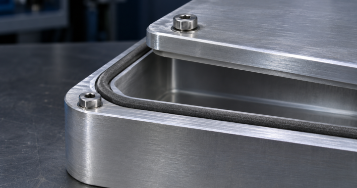
A lid can look flat at its fasteners while lifting slightly between them. That is enough to change the pressure on an EMI gasket. A section through the joint often tells the designer more than another torque value on the assembly drawing.
Control the closed gap at the lid
Let h0 be the uncompressed gasket height and g the closed gap between its contact surfaces.
C (%) = ((h0 − g) / h0) × 100
Check the gap at the loosest and tightest tolerance conditions, including lid deflection. Compare the resulting compression and closure load with the selected gasket’s data. Show the conductive contact land and the stop or other feature that limits closure on the drawing. Where moisture is expected, review the environmental seal and the corrosion resistance of the contact separately.
Detail the edge of a window and the frame of a vent
For a shielded display, the conductive film or mesh needs a defined connection at its edge to the bezel. A gasket pressing against plain glass leaves that connection open. For a honeycomb vent, show how its conductive frame bonds to the enclosure and check airflow with the actual filter and fan installed.
Draw the cable entry in section
Where an overall cable shield forms part of the RF boundary, show its circumferential connection through the connector or gland to the enclosure. A clamp gripping the insulating jacket provides strain relief. The drawing should show the separate contact to the shield. If the entry includes a filter, leave enough room to route the filtered and unfiltered leads apart.
GDS EMI/EMC Training
MIL-STD-461G EMI/EMC Testing covers emissions and susceptibility testing of military equipment.
RTCA-DO-160G Environmental Testing covers environmental and EMI/EMC testing of airborne equipment.