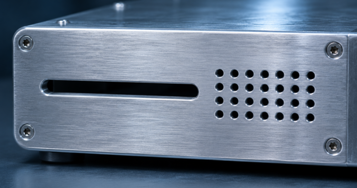
A vent can provide enough airflow and still leave a weak spot in an EMI shield. For a narrow slot, the dimension to check first is its length. As that length approaches half the wavelength of the interference, the slot can couple energy efficiently. A long gap around a removable cover deserves the same attention.
A 2.4 GHz example
Let L be the largest dimension of an opening and λ the wavelength in air. With both lengths in the same units, this relation gives a first estimate for a small aperture.
SEscreen ≈ 20 log10(λ / (2L)) dB
At 2.4 GHz, the wavelength in air is λ = c / f ≈ 125 mm. For a nominal screening estimate of 20 dB, divide both sides of the equation by 20. This gives log10(λ / (2L)) = 1, so λ / (2L) = 10.
L = λ / 20 = 125 mm / 20 = 6.25 mm = 0.625 cm
Halving the opening to 3.125 mm gives about 26 dB in the same model. Doubling it to 12.5 mm gives about 14 dB. These are estimates for the opening. Field orientation, nearby apertures, cable entries and enclosure resonances can change the result for the assembled unit.
When the opening has depth
A deep conductive channel can add attenuation below its cutoff frequency. Honeycomb vents use many such channels to let air through. Check the vent’s shielding data over the required band, the electrical contact around its frame and the pressure drop at the required airflow.
Download the GDS Metal Enclosure Design Guide (PDF)
Further reading · Practical EM Shielding
GDS EMI/EMC Training
MIL-STD-461G EMI/EMC Testing covers emissions and susceptibility testing of military equipment.
RTCA-DO-160G Environmental Testing covers environmental and EMI/EMC testing of airborne equipment.