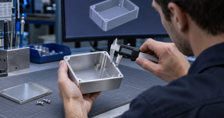
The enclosure layout decides where cables enter, where air flows and which panels technicians remove. Each decision changes how electromagnetic interference can get into or out of the product. Bring the electrical and test teams into that discussion while there is still room to move a connector or change a cover.
Agree what the enclosure has to protect
Electromagnetic compatibility (EMC) covers both what the product emits and how it behaves when exposed to interference. Before choosing a housing material, agree which frequencies matter, where the shielding boundary runs and what the equipment must do during immunity tests. Mark all the places where the boundary is crossed, from the power inlet to the display.
Put the electrical contact on the drawing
A drawing should show where mating surfaces must make conductive contact, where paint or anodizing must be kept clear, and how the assembly controls gasket compression. That information matters when a supplier changes the finish or a technician opens the cover for service. For accessible controls and connector shells, agree where an electrostatic discharge should travel through the chassis.
Test the configuration you plan to build
For early checks, fit the representative lid, vents, connectors and cables and run the operating modes that matter. If a temporary change to a seam or cable route improves the result, turn it into a drawing or assembly change and repeat the test. Review cooling, environmental sealing and intended radio operation alongside the EMC checks before release.
GDS EMI/EMC Training
MIL-STD-461G EMI/EMC Testing covers emissions and susceptibility testing of military equipment.
RTCA-DO-160G Environmental Testing covers environmental and EMI/EMC testing of airborne equipment.