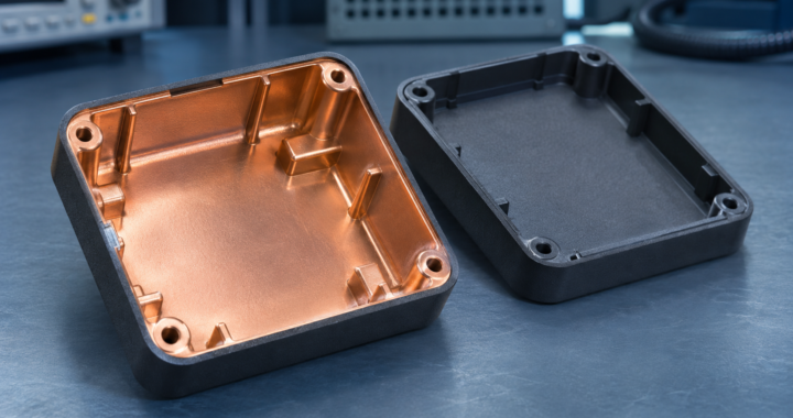
A molded plastic housing gives designers room to shape clips, bosses and curved surfaces into the part. When the housing also has to shield electronics from radio-frequency interference, those details affect where the conductive layer can run and how it connects across the finished assembly.
Coat the part or use a conductive compound
One approach is to add a conductive layer after molding. Conductive paint, electroless plating and vacuum metallization are common options. Pay particular attention to coverage inside recesses and around the gasket seats. Those are easy places to lose continuity or leave an area that is hard to inspect.
A second approach is to mold the part from a compound with conductive fillers, such as carbon or metal fibers. Ask for shielding data over the frequencies your product needs and check how the material behaves in the geometry you intend to mold. Include the actual lid and joint in that evaluation.
Follow the conductive path across the joint
Picture the path from one coated half of the housing, through the gasket, to the other half. Cosmetic paint or an insulating adhesive on that contact area can interrupt it. If the product contains an antenna, agree where the conductive layer should stop and check radio performance with the final housing fitted.
Use material data to shortlist options. Check the assembled housing with the actual seams, ports and cables in place.
Download the GDS Metal Enclosure Design Guide (PDF)
Related GDS article · Coatings and Paints for EMI-EMC Shielding
Further reading · What are EMI shielding plastics? (EMC Directory)
GDS EMI/EMC Training
MIL-STD-461G EMI/EMC Testing covers emissions and susceptibility testing of military equipment.
RTCA-DO-160G Environmental Testing covers environmental and EMI/EMC testing of airborne equipment.