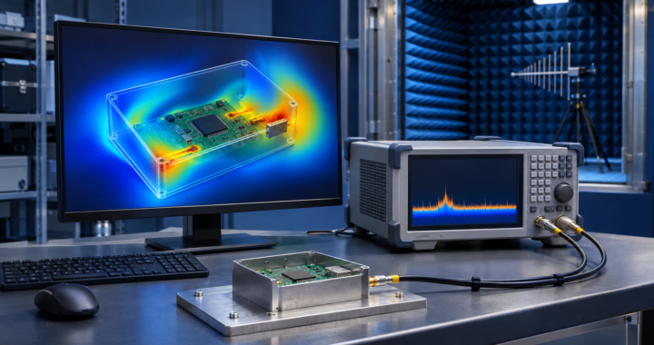
An emissions peak can raise two different questions. Where on the board is it coming from? Can we measure it again with the same settings and show how it compares with the limit? The 2026 GDS training compares the software used to answer those questions, from the design desk to the test laboratory.
Watch the software walkthrough with Dr. Ismail Cicek
Measurement and reporting in the laboratory
Packages such as R&S ELEKTRA, ETS-Lindgren TILE 8 and Raditeq RadiMation help run instrument sweeps, record test settings and prepare reports with limit lines. Start a comparison with the instruments already in the lab and the test methods the team runs. For a radiated emissions setup, include the receiver, antenna mast and turntable in that check.
Simulation and checks before formal testing
A 3D field solver such as Ansys HFSS or CST Studio Suite can help investigate coupling through an opening. PCB tools can help examine return paths or power distribution. Once hardware is available, a near-field scan can narrow down the source of a peak, and a repeatable pre-compliance setup can show whether a design change helped. Confirm performance on representative hardware using the applicable test methods and acceptance criteria.
The two-page comparison handout groups tools by laboratory and design use and gives a starting point for choosing what to evaluate.
Download the 2026 EMI-EMC Software Comparison Handout (PDF)
GDS EMI/EMC Training
MIL-STD-461G EMI/EMC Testing covers emissions and susceptibility testing of military equipment.
RTCA-DO-160G Environmental Testing covers environmental and EMI/EMC testing of airborne equipment.