
EMI-EMC Simulation, Analysis, and Test Software

An emissions peak can raise two different questions. Where on the board is it coming from? Can we measure it again with the same settings and show how it compares with the limit? The 2026 GDS training compares the software used to answer those questions, from the design desk to the test laboratory.

Watch the software walkthrough with Dr. Ismail Cicek

Measurement and reporting in the laboratory

Packages such as R&S ELEKTRA, ETS-Lindgren TILE 8 and Raditeq RadiMation help run instrument sweeps, record test settings and prepare reports with limit lines. Start a comparison with the instruments already in the lab and the test methods the team runs. For a radiated emissions setup, include the receiver, antenna mast and turntable in that check.

Simulation and checks before formal testing

A 3D field solver such as Ansys HFSS or CST Studio Suite can help investigate coupling through an opening. PCB tools can help examine return paths or power distribution. Once hardware is available, a near-field scan can narrow down the source of a peak, and a repeatable pre-compliance setup can show whether a design change helped. Confirm performance on representative hardware using the applicable test methods and acceptance criteria.

The two-page comparison handout groups tools by laboratory and design use and gives a starting point for choosing what to evaluate.

Download the 2026 EMI-EMC Software Comparison Handout (PDF)

GDS EMI/EMC Training

MIL-STD-461G EMI/EMC Testing covers emissions and susceptibility testing of military equipment.

RTCA-DO-160G Environmental Testing covers environmental and EMI/EMC testing of airborne equipment.

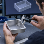
Mechanical Design Tips for EMI Shielding

A lid can look flat at its fasteners while lifting slightly between them. That is enough to change the pressure on an EMI gasket. A section through the joint often tells the designer more than another torque value on the assembly drawing.

Control the closed gap at the lid

Let h0 be the uncompressed gasket height and g the closed gap between its contact surfaces.

C (%) = ((h0 − g) / h0) × 100

Check the gap at the loosest and tightest tolerance conditions, including lid deflection. Compare the resulting compression and closure load with the selected gasket’s data. Show the conductive contact land and the stop or other feature that limits closure on the drawing. Where moisture is expected, review the environmental seal and the corrosion resistance of the contact separately.

Detail the edge of a window and the frame of a vent

For a shielded display, the conductive film or mesh needs a defined connection at its edge to the bezel. A gasket pressing against plain glass leaves that connection open. For a honeycomb vent, show how its conductive frame bonds to the enclosure and check airflow with the actual filter and fan installed.

Draw the cable entry in section

Where an overall cable shield forms part of the RF boundary, show its circumferential connection through the connector or gland to the enclosure. A clamp gripping the insulating jacket provides strain relief. The drawing should show the separate contact to the shield. If the entry includes a filter, leave enough room to route the filtered and unfiltered leads apart.

GDS EMI/EMC Training

MIL-STD-461G EMI/EMC Testing covers emissions and susceptibility testing of military equipment.

RTCA-DO-160G Environmental Testing covers environmental and EMI/EMC testing of airborne equipment.
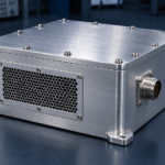
EMC for Mechanical Engineers

The enclosure layout decides where cables enter, where air flows and which panels technicians remove. Each decision changes how electromagnetic interference can get into or out of the product. Bring the electrical and test teams into that discussion while there is still room to move a connector or change a cover.

Agree what the enclosure has to protect

Electromagnetic compatibility (EMC) covers both what the product emits and how it behaves when exposed to interference. Before choosing a housing material, agree which frequencies matter, where the shielding boundary runs and what the equipment must do during immunity tests. Mark all the places where the boundary is crossed, from the power inlet to the display.

Put the electrical contact on the drawing

A drawing should show where mating surfaces must make conductive contact, where paint or anodizing must be kept clear, and how the assembly controls gasket compression. That information matters when a supplier changes the finish or a technician opens the cover for service. For accessible controls and connector shells, agree where an electrostatic discharge should travel through the chassis.

Test the configuration you plan to build

For early checks, fit the representative lid, vents, connectors and cables and run the operating modes that matter. If a temporary change to a seam or cable route improves the result, turn it into a drawing or assembly change and repeat the test. Review cooling, environmental sealing and intended radio operation alongside the EMC checks before release.

GDS EMI/EMC Training

MIL-STD-461G EMI/EMC Testing covers emissions and susceptibility testing of military equipment.

RTCA-DO-160G Environmental Testing covers environmental and EMI/EMC testing of airborne equipment.
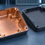
Metal Enclosure Design for EMI and EMC Protection

The wall of a metal enclosure may offer substantial shielding while interference still couples through the door joint or connector plate. Before specifying a material or gasket, draw the shielding boundary and mark every place where it is interrupted. That includes unused cutouts and removable panels.

What the GDS guide covers

The guide starts with the installation, the frequency range and the shielding performance the equipment needs. It then works through shell materials and finishes, lid and door joints, ventilation, power entry and cable shield termination. A separate section covers low-frequency magnetic fields, where material and geometry choices can differ from those used for RF shielding.

A worked example follows a ventilated metal enclosure from the initial layout to the checks needed for release. It shows how to screen an opening, assess a candidate vent and identify where measurements are needed. The design review worksheet gives teams a place to record each interface, its proposed treatment and the evidence required to close it.

Which configuration are you measuring?

A material sample, an empty enclosure and an operating product answer different questions. Record which configuration the data describe and verify the final equipment with its representative cables, loads and operating modes.

Download the GDS Metal Enclosure Design Guide (PDF)

GDS EMI/EMC Training

MIL-STD-461G EMI/EMC Testing covers emissions and susceptibility testing of military equipment.

RTCA-DO-160G Environmental Testing covers environmental and EMI/EMC testing of airborne equipment.

EMI Shielding for Plastic Enclosures

A molded plastic housing gives designers room to shape clips, bosses and curved surfaces into the part. When the housing also has to shield electronics from radio-frequency interference, those details affect where the conductive layer can run and how it connects across the finished assembly.

Coat the part or use a conductive compound

One approach is to add a conductive layer after molding. Conductive paint, electroless plating and vacuum metallization are common options. Pay particular attention to coverage inside recesses and around the gasket seats. Those are easy places to lose continuity or leave an area that is hard to inspect.

A second approach is to mold the part from a compound with conductive fillers, such as carbon or metal fibers. Ask for shielding data over the frequencies your product needs and check how the material behaves in the geometry you intend to mold. Include the actual lid and joint in that evaluation.

Follow the conductive path across the joint

Picture the path from one coated half of the housing, through the gasket, to the other half. Cosmetic paint or an insulating adhesive on that contact area can interrupt it. If the product contains an antenna, agree where the conductive layer should stop and check radio performance with the final housing fitted.

Use material data to shortlist options. Check the assembled housing with the actual seams, ports and cables in place.

Download the GDS Metal Enclosure Design Guide (PDF)

Related GDS article · Coatings and Paints for EMI-EMC Shielding

Further reading · What are EMI shielding plastics? (EMC Directory)

GDS EMI/EMC Training

MIL-STD-461G EMI/EMC Testing covers emissions and susceptibility testing of military equipment.

RTCA-DO-160G Environmental Testing covers environmental and EMI/EMC testing of airborne equipment.

EMI Shielding Concerns for Enclosures with Openings and Holes

A vent can provide enough airflow and still leave a weak spot in an EMI shield. For a narrow slot, the dimension to check first is its length. As that length approaches half the wavelength of the interference, the slot can couple energy efficiently. A long gap around a removable cover deserves the same attention.

A 2.4 GHz example

Let L be the largest dimension of an opening and λ the wavelength in air. With both lengths in the same units, this relation gives a first estimate for a small aperture.

SEscreen ≈ 20 log10(λ / (2L)) dB

At 2.4 GHz, the wavelength in air is λ = c / f ≈ 125 mm. For a nominal screening estimate of 20 dB, divide both sides of the equation by 20. This gives log10(λ / (2L)) = 1, so λ / (2L) = 10.

L = λ / 20 = 125 mm / 20 = 6.25 mm = 0.625 cm

Halving the opening to 3.125 mm gives about 26 dB in the same model. Doubling it to 12.5 mm gives about 14 dB. These are estimates for the opening. Field orientation, nearby apertures, cable entries and enclosure resonances can change the result for the assembled unit.

When the opening has depth

A deep conductive channel can add attenuation below its cutoff frequency. Honeycomb vents use many such channels to let air through. Check the vent’s shielding data over the required band, the electrical contact around its frame and the pressure drop at the required airflow.

Download the GDS Metal Enclosure Design Guide (PDF)

Further reading · Practical EM Shielding

GDS EMI/EMC Training

MIL-STD-461G EMI/EMC Testing covers emissions and susceptibility testing of military equipment.

RTCA-DO-160G Environmental Testing covers environmental and EMI/EMC testing of airborne equipment.